18-24 step LCD display Power factor regulator power factor relay PFC RVC,RVT
Switching strategy
Steps switching is based on the average value of the reactive power consumption of the load
during the switching delay time.
It allows:
• to control the PF in the presence of rapidly varying loads
• to use a longer switching delay time and as a result, to reduce the number of switchings.
On the basis of the reactive power demand measured during the switching delay time, the RVC
identifies the number of steps to be switched on.
It then automatically switches the bigger outputs first to avoid unnecessary intermediary
switchings.
During this switching sequence, a fixed 12-second delay time between each step is introduced
in order to avoid transient problems and to fulfil EMC requirements.
When several steps must be switched off, the controller does it in one shot because capacitor
switch-off is transient-free.
Default switching of steps is circular , however linear switching can also be done as explained in
the chapter 7.
Circular switching increases the lifetime of capacitors and contactors by balancing the switching
stress among all the outputs.
In case of “double first step” (1:1:2:2…; 1:1:2:4:4:…; 1:1:2:4:8:8:..), the circularity applies to the
first two outputs and also on the outputs of higher value.
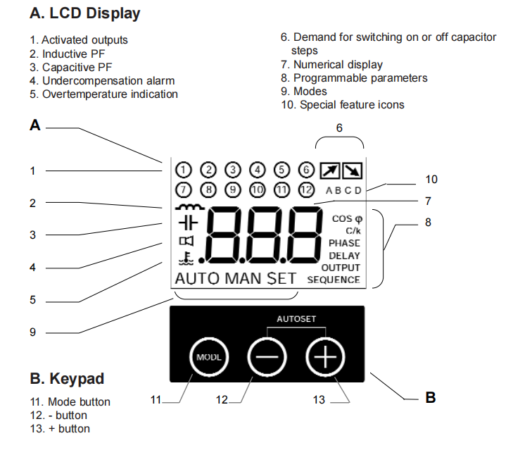
6. Modes
AUTO Mode
Steps are automatically switched on and off to reach the target cos ϕ according to the
measurement of the reactive current, the C/k setting, the switching delay, the number of
outputs and the type of sequence.
• The LCD display shows the actual cos ϕ.
MAN Mode
•
Steps are switched on and off manually by pressing + and - buttons.
The LCD display shows the actual cos ϕ.
AUTO SET Mode
Automatic setting of the following parameters:
• C/k: automatic setting of the sensitivity.
PHASE: automatic connection recognition (including inverted CT leads and single phase).
DELAY: automatic setting of the switching delay time to 40s.
OUTPUT: automatic recognition of number of outputs.
•
SEQUENCE: automatic recognition of type of sequence.
Factory default target cos ϕ : 1.00
MAN SET Mode
Manual setting of the following parameters:
• COS ϕ ϕ : target PF
• C/k: PF controller sensitivity
• PHASE: phase connection
• DELAY: switching delay time
• OUTPUT: number of outputs
• SEQUENCE: type of sequence
7. Programmable parameters
COS ϕ ϕ
It is the target power factor that the PF Controller has to reach by switching steps. The value can
be set between 0.70 inductive and 0.70 capacitive in the Manual Set Mode (MAN SET – COS ϕ).
An alternative generative / regenerative power factor may be activated. So, when the power flow
is reversing (P < 0), the target power factor is forced to 1.0 (see chapter 8).
C/k
C/k is the sensitivity of the PF Controller. It is usually set equal to 2/3 of the current of the first
capacitor step. It represents the threshold current value for the PF Controller to switch on or off
a capacitor step. The C/k can be programmed from 0.050 to 1.00.
The value can be set either automatically (AUTO SET) or manually (MAN SET – C/k).
Phase shift
If the RVC is connected as shown on the connection diagram of the PF Controller, the phase shift
is 90° (default setting). For special connections, please refer to chapter 11 – Programming.
Setting the phase shift may be done either automatically (AUTO SET) or manually (MAN SET –
PHASE).
Overvoltage / Undervoltage
The user can set upper and lower threshold limits in voltage. The RVC allows disconnection of
all the steps in case the voltage exceeds preset threshold limits.
Linear / Circular
Linear switching follows the “first in, last out” switchings principle whereas the circular switching
follows the “first in, first out” switchings principle. Circular switching increases the lifetime of
capacitors and contactors by balancing the stress among all the outputs (default setting).
Switching delay
The default value of the switching delay time between steps is 40s and can be programmed from
1s to 999s. Setting of switching delay time may be done manually (MAN SET – DELAY).
Output
Output represents the number of physical outputs and can be programmed from 1 to 12
according to the RVC type. Setting the output may be done either automatically (AUTO SET) or
manually (MAN SET – OUTPUT).
Sequence
Switching sequences allowed by the RVC Controllers are: