


|
No |
Description |
Unit |
Data |
|
1 |
Maximum system voltage |
kV |
40.5 |
|
2 |
Rated Voltage |
kV |
30、33、36 |
|
3 |
Rated Current |
A |
630 ,1250 ,1600,2000,2500,3150,4000 |
|
4 |
Rated Frequency |
Hz |
50/60 |
|
5 |
Rated short-time withstand current |
kA |
25、31.5、40 |
|
6 |
Rated Peak withstand current |
kA |
50、63 |
|
7 |
Rated power frequency withstand voltage |
kV |
85/1min |
|
8 |
Rated impulse lightning withstand voltage |
kV |
185 |
|
9 |
Rated short circuit duration |
s |
4 |
|
10 |
Protection level |
|
IP4X |
|
No |
Description |
Unit |
ZN85 Data |
|
1 |
Rated Voltage |
kV |
40.5 |
|
2 |
Rated Current |
A |
630 ,1250 ,1600,2000,2500,3150 |
|
3 |
Rated Frequency |
Hz |
50/60 |
|
4 |
Rated short-time withstand current |
kA |
25、31.5、40 |
|
5 |
Rated short circuit break current |
kA |
25、31.5、40 |
|
6 |
Rated Peak withstand current |
kA |
50、63 |
|
7 |
Rated power frequency withstand voltage |
kV |
85/1min |
|
8 |
Rated impulse lightning withstand voltage |
kV |
185 |
|
9 |
Rated short circuit duration |
s |
4 |
|
10 |
Open time |
ms |
30≤t≤60 |
|
11 |
Close time |
ms |
50≤t≤100 |
|
12 |
Rated short circuit break current numbers |
|
2 |
|
13 |
Mechanical Endurance |
Times |
10000 |
|
No |
Description |
Unit |
Data |
|
|
1 |
Rated Voltage |
Open coil |
V |
DC220/110 AC220/110 |
|
Close coil |
||||
|
2 |
Rated operate current |
Open coil |
A |
0.96(220 V) 1.05(110V) |
|
Close coil |
||||
|
3 |
Spring charge motor |
W |
230 |
|
|
4 |
Spring charge motor rated voltage |
V |
DC220/110 AC220/110 |
|
|
5 |
Spring charge time |
S |
≤12 |
|
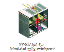
1. Enclosure and partition
The Enclosure and partition plate of the switchgear is made of cold rolled steel plate after being processed by a numerical control machine and bolting by benting . As a result, the assembled switchgear can ensure the unity of the structural dimensions. Switchgear is divided into circuit breaker chamber, the main bus chamber, cable chamber and the relay instruments chamber, each parts to be separated by a grounded metal partition.
2. Handcart
According to handcart using purpose , it can be divided into the circuit breaker handcart , the voltage transformer handcart , measuring handcart isolation handcart , etc., all kinds of handcart outline dimension is same , the using purpose of handcart with interchangeability. Handcart has test /isolation position and service position, each position is equipped with interlocking devices to ensure that the handcart can not move when it is in above test /isolation position and service position.
3.Circuit Breaker Compartment
The circuit breaker compartment is fitted with the necessary guide rails to accommodate the withdrawable part,which can be moved between the service position and the test position. The isolation valve is automatically opened or closed to ensure staff not touch the charged body.The withdrawable part can be operated when the door of panel closed.through the observation window to see the handcart in the cabinet position , at the same time to see any function signs on the handcart.
4.Bus Compartment
Main bus are laid in sections from panel to panel by branch small bus and fix contacts box to fix .Across side board of the adjacent cabinet with bus bushing to fix. All buses adopt composite insulation.
5. Cable Compartment
Cable compartment can be installed PT, earthing switch, lightning arrester and a plurality of cables.
6. Relay Compartment
Relay compartment inner board and panels can be installed to control, protection components, measurement, display instruments, live monitoring indicators etc secondary components.
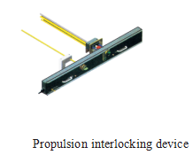
7. Interlocks device
●Switchgear has reliable interlock device to ensure the safety of operators and equipment:
●When the earthing switch in the off position, the truck can move from the test / disconnected position to the service position and the back door can not be opened to prevent accessing into live space.
●When the truck pulled completely out of cabinet outside or truck in the test/isolation position in the cabinet and the earthing switch interlocking can unlock , the earthing switch can close operation; The truck is in the working position, earthing switch can not be closed to prevent the earthing switch mal-closing with the electrification and prevent the earthing switch in the closed position when the truck moved to the service position.
●The circuit breaker truck in the test / disconnected position or working position, we can operate circuit breaker ; after circuit breaker closed ,the truck can not move to prevent mal- pushing and mal-pulling circuit breaker under charged load
●The electric interlocking can be installed between cabinets .
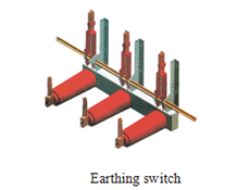
8.Earthing device
In the cable chamber, alone with Φ6× 50mm2 grounding bus, which can run through the adjacent cabinets, and good contact with cabinets

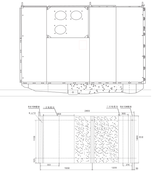
|
Outline dimension (W×D×H)mm: |
Switchgear structure sketch |
|
|
A Relay instruments chamber |
B Bus chamber |
|
|
1400×2800×2600 |
C Circuit beaker chamber |
D Cabl e chamber |
|
1200×2800×2400 |
||
|
1200×3000×2600 |
||
1.Height of electrical room: ≥4500mm;
2. Distance from cabinets back to wall: ≥1500mm;
3. Basic frame of flatness: ≤1 mm/m2;
4.Based on embedded channel higher ground shall not exceed 3mm;
5. Available bolts or welding can be fixed on the foundation;
6. Switchgear weight about :1800Kg;
7. Switchgear operating corridor width (single row): ≥3000mm,double row (face to face ) ≥4000mm.