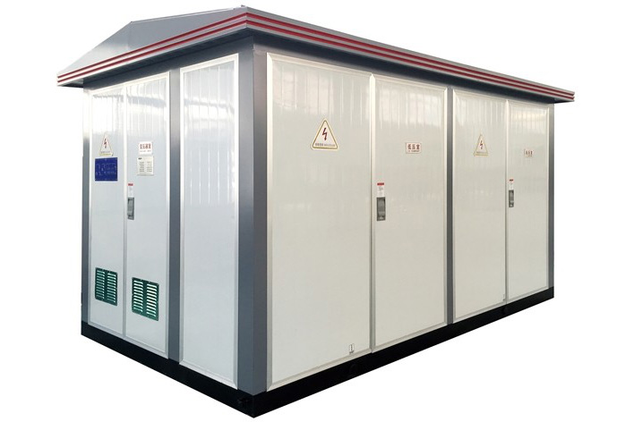


1.Compact Substation should meet the following requirements:
1)Inspection certificate and accompanying technical documents, with a factory test records;
2)Visual inspection: Nameplate, completely accessories, insulation items without defects, cracks, part of oil-filled no leak-out, inflatable pressure high-voltage equipment indicating normal, coating integrity.
2.Construction process and description
1)The construction process Laying based steel → laying ground grid →compact substation handling →compact substation installation → cable termination connection.
2)Process Description Laying based steel (1)Indoor base of cable and based platform with 1:25 concrete mortar surface, thickness of 20mm, the surface to be smooth.
(2)The basis of steel should be strictly in accordance with the drawings and specifications to lay and be treated with preservatives.
(3)Equipment installation of fasteners should be used in galvanized to all products (except bolt outside).
(4)To install its equipment base steel tolerances are shown in Table 8.2-5. Table 8.2-5 base steel installation tolerances
|
Project |
Allow tolerance |
|
|
mm/m |
mm/ total long |
|
|
No vertical |
1 |
5 |
|
Level |
1 |
5 |
|
Position error & no parallel |
|
5 |
(5)After installing basic steel, its top should be higher than the flat ground 10mm, base-steel should have more than two place to reliable grounding
(6)Compact Substation between the base and the foundation to use cement mortar seal so as to avoid rain water into the compact substation ; After the cable into the Compact Substation, the gap between cable and pipe required to waterproof and seal; The bottom of compact substation need to slightly tilted to avoid water
(7)The number of inlet and outlet and the cable diameter, can be determined according to the actual situation of the user's location and the inlet and outlet , spacing of pipe row not less than 30mm
3.Laying ground grid Grounding device should comply with DL / T 621-1997 "grounded AC electrical installations" requirements.
4.Precautions for installation of hoisting and transportation:
1).The grounding electrode should be pre buried around the foundation of Compact substation. The transformer & anti-lightning grounding can be used together, the grounding resistance R <4Ω.
2).Application of special lifting tools for Compact substation hoisting, the lifting part must be according to the marked location of the Compact substation .The connection place of bottom & foundation of Compact substation need to be sealed by cement for waterproof.
3).The gap must be sealed after the cables go into the bushing for insect prevention and waterproof.
4)..It must check below conditions before the transportation :
The connection place of its bottom and the foundation must be smooth. If open the doors with stuck phenomenon , because of uneven foundation, So it must adjust the connection place to be even.
Adjustment method : slitting thin iron sheet on the gap between the Compact substation bottom side and base gap until the door opening flexible. When the Compact substation is completely assembled, loadingmust pay attention to keep a certain distance between the whole Compact substation and the front of the vehicle to prevent the car front and rear crash due to brake , while bottom frame of Compact substation and car bottom must use welding to fix, then using steel wire to chassis vehicle bottom and bottom frame , and using rope from the top to the car to make it fix a few low on the road. Where the ropes are bent, the boards must be lined with cardboard or other soft materials to protect the surface of the coating from damage. In order to keep the box type station in operation intact, it is better to clean and wipe the interior and exterior after power cut for one year.If it is found that the outer surface of the Compact substation is contaminated after the installation, it can be wiped with detergent and rinsed with clean water.
5.After fininshed installation, each cabinet room of compact substation need to a comprehensive inspection, the main contents as follows:
(1)Check the drawings, view the device components, whether wiring, are consistent with designed or not
(2)Checking the phase sequence is correct.
(3)Adjusted five against mechanical locking device, requiring flexible and reliable. (4)Adjustment switch, grounding switch, require fast, reliable, good contact.
6.Cable termination connection
Primary, secondary wiring of compact substation, the control lines should be connected correctly, and connecting should comply with the relevant regulation of «cable termination»
III.inspection and testing
1.Quantitative detection
1)Transformers, high and low voltage cabinet over test
2)Transformers withstand voltage test.
3)24h load test.
2.Qualitative examination 1)"Five Anti" function tests.
2) Measurement, protection and monitoring function tests. 3 )Open and close function tests.
4) Phase Check.
5)Check the safety facilities.
IV.O ther
1.After the installation is completed, aside nozzle holes and outdoor Compact (subtation) should be prepared within the block, referred to freeze the area, it should be measures to prevent freezing of water inside the tube.
2.The switch of outgoing should be marked direction, that the name of the user to the location
3.Shell of substation should paint or install the safety warning signs"Beware of electric shock", "high hazard, do not touch" and other

Complete set to provide the following documents
1 Product packing list;
2Product factory test report;
3Product manual instruction;
4Equipment list;
5Secondary wiring diagram;
6The products are supplied according to the catalog and equipment list;
Pls kindly supply following information ,if you have any enquiry on Compact substation
1)Altitude : ≤1000m or ≥1000m
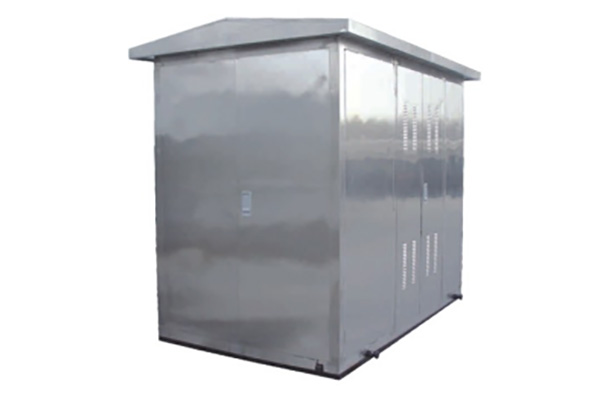
2)Outdoor enclosure material: Composite plate or Metal cold rolled sheet
3)HV Room request:
|
(a) Switch type : |
(1) Fix or withdrawable |
|
(2) Rated current |
|
|
(3) Rated voltage |
|
|
(4) IP protection |
|
|
(b)INCOMER |
(1) LBS or VCB |
|
(2) Operation method : Manual or |
|
(c)OUTGOING |
(1)LBS or VCB or fuse load break switch |
|
(2)Operation method : Manual or Motorised |
|
|
(3) PT loop request or not |
|
Capacity (kVA) |
|
Losses request: |
|
Rated voltage ratio (kV) |
|
No load losses(W) |
|
Frequency: 50Hz or 60Hz |
|
Load losses (W) |
|
LV incoming |
ACB |
(a)Fixed (b)withdraw |
3P |
or 4P |
|
|
MCCB |
(a)Fixed (b) withdraw |
3P |
or 4P |
||
|
LV outgoing |
Loop quantity |
||||
|
LV outgoing |
(a)Fixed |
(b)withdraw (c) Fuse |
3P |
or 4P |
|
|
|
Item |
Unit |
Parameter |
|||
|
High Voltage Unit |
Rated frequency |
Hz |
50/60 |
|||
|
Rated Voltage |
kV |
11 |
13.8、15 |
20、22 |
30,33,36 |
|
|
Max service voltage |
kV |
12 |
17.5 |
24 |
40.5 |
|
|
Rated current |
A |
400、630、1250、1600、2000、 |
||||
|
transformer current |
A |
400~5000 |
||||
|
|
1min power frequency withstand voltage to earth and phase |
kV |
42/48 |
48/55 |
55/65 |
85/95 |
|
BIL: to earth and phase to phase |
kV |
75/85 |
90/105 |
125/150 |
170/185 |
|
|
Rated short circuit breaking current |
kA |
25、31.5、40 |
||||
|
Transformer Unit |
Rated Voltage |
kV |
11、13.8、15、20、22、30、33、36 |
|||
|
Rated Capacity |
kVA |
160~2500 |
||||
|
Tap ranging |
% |
+/-2x2.5%、+/-5% |
||||
|
Vector Group |
|
Yyn0、Dyn11 |
||||
|
Impedance |
% |
4、4.5、6、8 |
||||
|
Low Voltage Unit |
Rated Voltage |
V |
220、400、690、800 |
|||
|
Main circuit rated current |
A |
400~5000 |
||||
|
Branch current |
A |
63-1250 |
||||
|
Enclosure |
Protection Level |
|
HV Room:IP44 |
|||
|
Noise level |
dB |
≤50 |
||||

|
1.Roof |
4.Lifting ring |
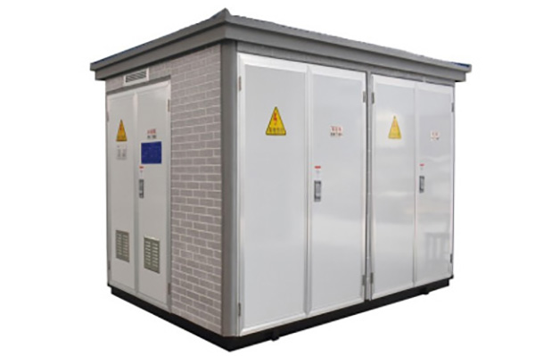
7. Brick, imitation brick wall |
|
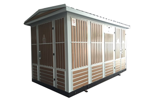
2 shutters |
5. Channel base |
8.Concrete foundation |
|
3. External metering unit |
6. Door |
9.Foundation vents |