


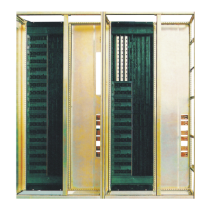
Its basic structure is an assembly of C type profiles which made from plate bending with E=25 module installation hole. The whole cabinet and inner compartments are purification treatment of zinc plating. The door panels and side panels are electrostatic sprayed.The cabinet basic structure is as picture.1 and basic size as picture.2 (table 1 and 2)
1.Power Distribution Center switchgear (PC): can adopt Emax,MT,3WN,AH,ME series circuit breakers. 2.Motor control center switchgear (GCK、GCS、MNS) : it is the assembly of big & small drawer, every circuit main switch is high breaking moulded case circuit breaker or rotation type load break switch with fuse. Power factor automatic compensation cabinet is with manual or automatic and remote power factor compensation device.
A Power distribution center (PC) cabinet
|
Height |
Width |
Depth |
Remark |
||
|
H |
B |
T |
T1 |
T2 |
|
|
2200 |
400 |
1000 |
800 |
200 |
Main bus transfer |
|
2200 |
400 |
1000 |
800 |
200 |
F s-1250-2000 ME630-1605 |
|
2200 |
600 |
1000 |
800 |
200 |
F s-2500 |
|
2200 |
800 |
1000 |
800 |
200 |
F s-3200 ME2000-3200 |
|
2200 |
1000 |
1000 |
800 |
200 |
F s-4000 ME3205 |
|
2200 |
1200 |
1000 |
800 |
200 |
ME4005 |
B Power distribution center (PC) cabinet
|
Height |
Width |
Depth |
Remark |
||||
|
H |
B |
B1 |
B2 |
T |
T2 |
T2 |
|
|
2200 |
1000 |
600 |
400 |
600 |
400 |
200 |
Single-side operation |
|
2200 |
1000 |
600 |
400 |
1000 |
400 |
200 |
Double-side operation |
C type composed frame structure (Figure 1)
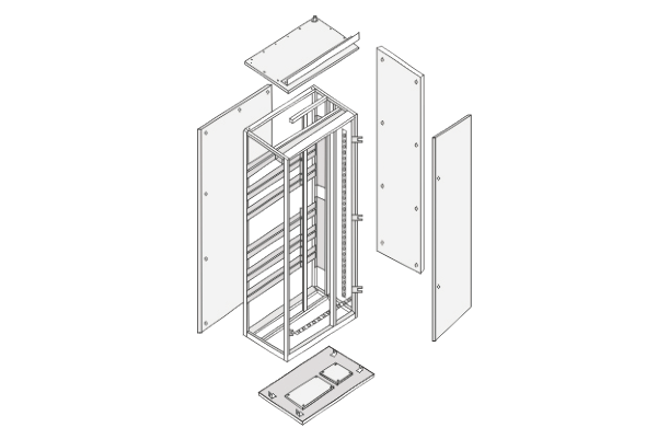
Schematic diagram of cabinet (Fig 2)

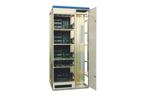
1)Power distribution center (PC).
(1)In the PC cabinet ,there has 3 compartments.
The horizontal busbar compartment is at the back of the cabinet.
Function unit compartment is at the front of cabinet or the left of cabinet.
(2)The way of compartment: use steel plate between the horizontal busbar compartment and function unit compartment. Use flame retardant polyphenylene oxide plastic shell between the circuit controlling compartment and function unit compartment.
(3)Inner installed air circuit breaker ,which can be operated by manual at outside cabinet when the door is closed. To determine whether the circuit breaker is in the test position or in the service position by observing circuit breaker ON-OFF state and the position between door and controlling systems.
(4)Between the main circuit and auxiliary circuit ,designing the compartments structure to auxiliary electric units like instrument, signal lamps & push buttons etc ,which are fixed on the plastic plate . At the back of this plate, the shell made of flame retardant polyamine foam plastics ,which is separated from the main circuit.
2)Withdrawable type motor control center & small current power distribution center (GCK、GCS、MNS):
Withdrawable GCK、GCS、MNS cabinet ,there also has 3 compartments, that is horizontal busbar compartment at the back of the cabinet, function unit compartment at the front left of the cabinet, cable compartment at the right of the cabinet. Separation of functional panel made of flame retardant foamed plastics between the horizontal busbar compartment and functional units compartment. Separation of steel panel between cable compartment, horizontal busbar compartment and functional unit compartment.
|
8E/4: 200(H) x 150(W) x 400(D) mm |
8E/2: 200(H) x 300(W) x 400(D)mm |
|
8E :200(H) x 600(W) x 400(D) mm |
16E: 400(H) x 600(W) x 400(D) mm |
|
24E: 600(H) x 600(W) x 400(D) mm |
|

3)The rear structure of outgoing :
This back outlet is designed for decreasing the arrangement width of the switchgear. Its main busbar is installed horizontally on the top of the cabinet, on the half of back is cable compartment. The incoming cables are all connected in this cable compartment. The front of the switchgear is a device small chamber to install functional units or parts. This system design will move the cable compartment at the side of the panel back ,which hardly decrease the arrangement width of cabinets to further satisfy the space requirements of power substation.
The width of feeder panel is 600mm,depth 1000/1200 mm. On its top, it is independent of the main bus compartment separated from device small chamber. The height of front device chamber is 72E(E=25mm) which separated from the back cable compartment through the multi-functional panel, fully usage of installation space of the cabinet. Its structure is compact & flexible unit configuration. The back cable compartment is with the door for convenient installation & maintenance . The width of incoming is according to the frame-current of incoming units . Advised width is 400/600/800/1000mm,cabinet depth 1000mm.
It can be equipped with 2 groups busbar which installed at the back busbar compartment of the switchgear. They are installed upper and lower back of cabinet. According to the needs of the incoming , up and down two sets of busbar can be adopted the materials with same or different cross-section. They can supply power separately ,also can supply power in parallel connection or as backup power source.

The protection circuit is made from electrically conductive structural devices & PE lines( or PE/N lines) that are individually mounted and run through the entire length of the array . For the metal structural devices or parts, except the exterior door and seal plates, others are treated by zinc-coated.At the place of structural parts connection , do the carefully design to pass a certain short-circuit current.
The auxiliary circuit cable tray is installed at the top of the compartment of the functional unit, and the connection line and the common power line can be put in the tray.
At the side of withdrawable parts ,in the cable small chamber installed cable connection devices and terminals for connecting outlet cable and controlling line and devices. The wiring device is arranged in the chamber on the right side of the rail cable; Main circuit terminal is at the back; Control terminal is at the front 45°direction.Use screws to connect wires for control terminal or use copper lugs or plug-in type cable lugs. The main circuit terminal of the transfer parts is less than 63A , also with PE terminal blocks.
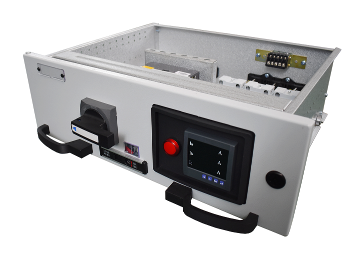
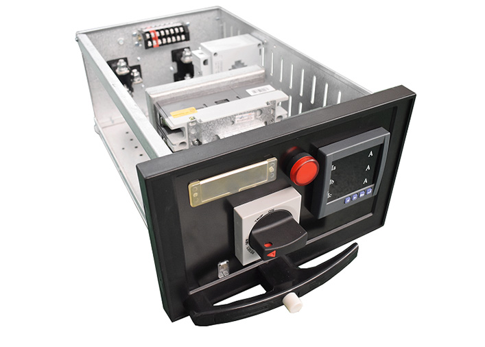
There has 5 standard sizes based on height of 8E (200mm)
8E/2: assembly 2PCS drawer type units in 8E space.
8E/4: assembly 4PCS drawer type units in 8E space.
8E: assembly 1PC drawer type unit in 8E space
16E: assemble 1PC drawer type unit in 16E (400mm) space
24E: assembly 1PC drawer type unit in 24E (600mm) space
5 types of drawer unit can be assembled in a single cabinet ,can be mixed assembled too. If assembled in a single cabinet, the max drawer No. is as parameter 3.
|
Drawer type |
8E/4 |
8E/2 |
8E |
16E |
24E |
|
Maximum number of units accepted |
36 |
18 |
9 |
4 |
3 |
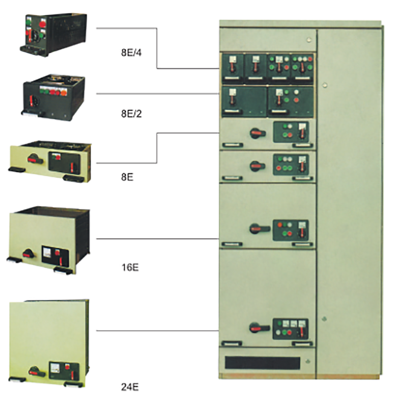

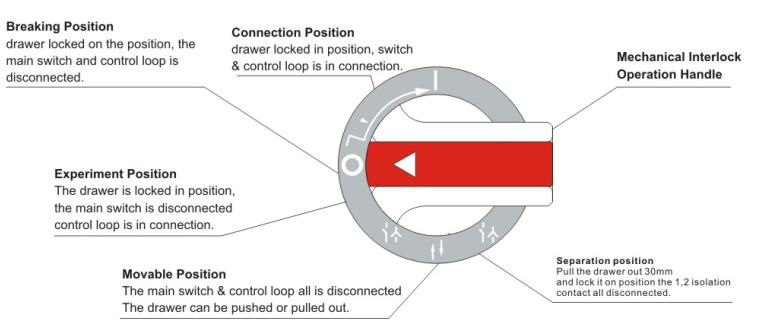
Figure 4 8E/4 and 8E operating switch function
|
Rated insulation voltage |
690V(1000)V |
|
Rated working voltage |
380V,400V,690V |
|
Maximum working current of main bus |
6300A |
|
Rated withstand current of main busbar |
100kA/1s |
|
Main busbar rated peak withstand current |
220kA/0.1s |
|
Maximum operating current of branch distribution bus (vertical bus) |
2000A |
|
Peak current of distribution bus (vertical busbar): |
|
|
Standard type |
105kA(Max)/0.1s |
|
Reinforced type |
176kA(Max)/0.1s |
|
Protection level |
IP41 |


